For a recent project I had the need to control stepper motors using a Raspberry Pi 4.
I’m writing this article to share my methodology and knowledge gained with those who have similar motion control needs.
The Requirements
First, let’s consider the project requirements.
The piece of equipment I was working on is an automated slide stainer for a robotics start-up.
The device needs to move a rack of microscope slides into beakers with different chemical reagents
at programmable intervals.
Therefore, I needed a motion control system with high repeatability, but with lower precision and torque
requirements. As long as the slides get into the beaker, it’s a success.
Because of this, I was able to start with a smaller, lighter motor package than might be needed
on a higher torque/precision machine such as a CNC router.
The Setup
The device is powered by a Raspberry Pi 4.
The decision is largely driven by the power, cost, and availability of compatible components.
The Pi 4 comes with Wi-Fi built in and, coupled with a 7″ touch-screen, gives a solid platform for an IoT
edge device for under $115.
Having a controller as powerful as the Pi comes with the advantage a choice of programming
technologies and makes networking and setting up a touchscreen trivial.
It also comes with the disadvantage of much less control over the timing of generated
waveforms than a traditional microcontroller.
For motors, I chose steppers as a tried-and-true solution for precise motor control at this scale.
To drive the steppers, I’m using the DM320T controller.
These take three inputs: an enable signal, a direction signal, and a pulse signal.
According to the timing diagram on the datasheet, I can generate a signal
with a width as small as 7.5 micro-seconds.
The stepper motor I’m using is a NEMA 8 bipolar stepper with 3Ncm of torque.
The Code
I chose to program this in Clojure due to the fast, tight development cycle enabled by hot-reloading
as well as the speed, quality, and enjoyment of language features such as easy immutable data
structures and inline unit tests.
I chose to use the dvlopt.linux.gpio library for handling GPIOs:
(ns slide-stainer.core
(:require [dvlopt.linux.gpio :as gpio]))
Next I defined the pin setup.
Some parts of the pin setup, such as :position or :travel_distance_per_turn, are for usage outside the scope of this article.
(defonce state-atom (atom {}))
(defonce pulse-lock (atom false))
(def pin-defs
     {:stepperZ {:pins
                 {17 {::gpio/tag :stepperX-ena
                  :inverted? false}
                 18 {::gpio/tag :stepperX-dir
                  :inverted? false}
                 19 {::gpio/tag :stepperX-pul
                  :inverted? false}}
                  :travel_distance_per_turn 0.063 ; distance traveled by the ACME lead screw nut, in inches per turn
                  :position nil
                  :position_limit 9
                  :pulses_per_revolution 800}})
I also wrote a tag to map that into the format needed by the GPIO library.
Note the inline unit test using the with-test macro, which is one of Clojure’s handy features
that keeps sample usage of a function right next to the definition of the function:
(with-test
  (defn get-pin-defs-for-gpio-lib [pin-defs]
    (apply merge (map (fn [[device {pins :pins}]]
                        (apply merge (map (fn [[pin_num {tag ::gpio/tag}]]
                                            {pin_num {::gpio/tag tag}}) pins))) pin-defs)))
  (let [sample-pin-defs {:stepperX {:pins
                                    {17 {::gpio/tag :stepperX-ena
                                         :inverted? true}
                                     18 {::gpio/tag :stepperX-dir
                                         :inverted? true}
                                     19 {::gpio/tag :stepperX-pul
                                         :inverted? true}}
                                    :pos nil
                                    :pos-limit-inches 9}
                         :stepperZ {:pins
                                    {20 {::gpio/tag :stepperZ-ena
                                         :inverted? true}
                                     21 {::gpio/tag :stepperZ-dir
                                         :inverted? true}
                                     22 {::gpio/tag :stepperZ-pul
                                         :inverted? true}}
                                    :pos nil
                                    :pos-limit-inches 4}
                         :led12 {:pins
                                 {12 {::gpio/tag :led12-led
                                      :inverted? true}}}}
        pin-defs-for-lib {12 {::gpio/tag :led12-led}
                          17 {::gpio/tag :stepperX-ena}
                          18 {::gpio/tag :stepperX-dir}
                          19 {::gpio/tag :stepperX-pul}
                          20 {::gpio/tag :stepperZ-ena}
                          21 {::gpio/tag :stepperZ-dir}
                          22 {::gpio/tag :stepperZ-pul}}]
    (is (= pin-defs-for-lib (get-pin-defs-for-gpio-lib sample-pin-defs)))))
Next is a helper function to load that all into a state atom.
It’s preferable to avoid global state but, in the case of GPIO lines, you only have one set on
the board, so you’re forced to keep a global state. For I/O, side effects is the name of the game.
(defn init-pins
  ([] (init-pins state-atom))
  ([state-atom]
   (swap! state-atom assoc :device (gpio/device 0))
   (swap! state-atom assoc :handle (gpio/handle (:device @state-atom)
                                                (get-pin-defs-for-gpio-lib (:setup @state-atom))
                                                {::gpio/direction :output}))
   (swap! state-atom assoc :buffer (gpio/buffer (:handle @state-atom)))))
Finally, we can define a help tag that takes the keyword name of a pin (like :stepperX-ena) and
a logical value and sets it:
(defn set-pin [pin-tag state]
  (when (not (:device @state-atom)) (init-pins))
  (println "Setting pin " pin-tag " to " state)
  (gpio/write (:handle @state-atom) (-> (:buffer @state-atom) (gpio/set-line pin-tag state))))
A simple test with an LED showed that that worked, so it’s on to writing the pulsing function.
It grabs a lock since my RESTful web server can take multiple requests in to pulse the motor,
and we can’t have multiple threads using the pin at the same since that would garble the
waveform. Typically examples with waiting in Clojure use the Thread/sleep API, but
I chose to use java.util.concurrent.locks.LockSupport/parkNanos due to the higher resolution.
(defn pulse [pin-tag wait-ns num-pulses]
  (println "Starting pulse" wait-ns num-pulses)
  (if (compare-and-set! pulse-lock false true)
    (do
      (println "Grabbed the lock" wait-ns num-pulses)
      (loop [i num-pulses]
        (when (> i 0)
          (set-pin pin-tag true)
          (java.util.concurrent.locks.LockSupport/parkNanos wait-ns)
          (set-pin pin-tag false)
          (java.util.concurrent.locks.LockSupport/parkNanos wait-ns)
          (recur (- i 1))))
      (when (not (compare-and-set! pulse-lock true false)) (println "Someone messed with the lock"))
      (println "Finishing pulsing" wait-ns num-pulses))
    (println "Couldn't get the lock on pulse")))
Analysis of the Generated Waveform
At this point, it’s time to measure the waveform to see how well the Pi is doing with generation.
When I’m not at the lab, I use a little mini-oscilloscope in my home office called the XProtoLab.
It’s an AVR with a little screen that displays waveforms.
It can’t handle high-frequencies, but since the signal I’m looking at is slow it works fine.
Using this, I generated the following table of test data:
| Time to Wait | Length of one period | Freq (Hz) |
|---|---|---|
| 10000 us | 21.25 ms | 47 |
| 5000 us | 10.62 ms | 94 |
| 2500 us | 5.625 ms | 177 |
| 1000 us | 2.5 ms | 400 |
| 500 us | 1.187 ms | 842 |
| 250 us | 1.125 ms | 888 |
| 100 us | 400 us | 2500 |
| 50 us | 312 us | 3205 |
| 10 us | 416 us | 2403 |
| 1 us | 80 us | 12500 |
| 500 ns | 176 us | 681 |
| 250 ns | 88 us | 11900 |
Note that for a few data points,
lowering the time-to-wait from 500 ms to 100 ms didn’t actually have an effect.
At lower frequencies it scaled linearly, and produced the expected waveform (the length being roughly
twice the time-to-wait), but at higher frequencies the Pi struggled to generate a signal fast enough.
(Brief footnote: to be precise, the version of the code that I used to generate this table lacked the pulse-lock
locking mechanism. I don’t think this had an effect on the results).
Review of the code revealed a simple bug: I left a println in the set-pin function.
While useful when doing initial testing to blink an LED, it was now writing thousands of lines
to standard output.
Taking the println out led to much better results, with a top achievable frequency of around 77kHz:
| Time to Wait | Length of one period | Freq (Hz) |
|---|---|---|
| 10000 us | 20 ms | 50 |
| 5000 us | 10 ms | 96 |
| 2500 us | 5625 us | 178 |
| 1000 us | 2112 us | 473 |
| 500 us | 1168 us | 856 |
| 250 us | 656 us | 1524 |
| 100 us | 332 us | 3012 |
| 50 us | 244 us | 4000 |
| 10 us | 152 us | 6578 |
| 1 us | 76 us | 13150 |
| 500 ns | 13 us | 76920 |
| 250 ns | 13 us | 76920 |
Implementing a Ramp-Up
Having a relatively reliable pulse-generator in hand, I started testing the behavior with the
stepper motor. This worked well at lower frequencies and led to no noticeable drift in the position
of the motor after sending an instruction to turn four full turns.
At higher frequencies it became clear that steps were getting missed.
One possible reason that stepper motors can miss steps is if too high of an acceleration is
attempted
This is because the coil engagement pattern changes before the motor stator can reach the desired
position.
I found this article
to contain some useful explanations of why steps can be missed.
The solution to this is to implement a ramp-up/ramp-down mechanism inside the pulse generator.
At slow speeds a lower frequency needs to be used until the stator can get up to speed.
At this point, it’s important to decide which units to use for determining the solution.
An ideal solution would take into account the load being driven by the stepper and be calculated
in terms of RPM and distance traveled.
Since the load on the stepper for my application is not variable, I chose to express the velocity
of the motor in Hz and the distance traveled in number of steps.
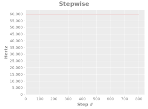
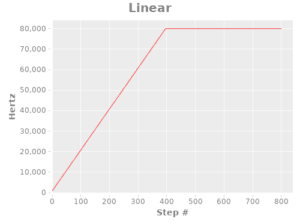
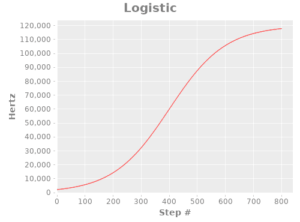
First, I implemented three pulse generation functions: a stepwise one (for illustration), a linear one, and one based off of the logistic function:
(ns ramp-up.core
  (:require [incanter.core :refer :all]
            [incanter.io :refer :all]
            [incanter.stats :refer :all]
            [incanter.charts :refer :all])
  (:use [clojure.test])
  )

(defn pulse-step-fn
  "Stepper pulse generation function that always outputs a 60kHz signal"
  [step]
  60000)

(defn pulse-linear-fn
  "Stepper pulse generation function that uses a linear ramp-up"
  [step]
  (let [slope 100
        initial_offset 80]
    (min
     (+ (* step slope) initial_offset) ; y = mx+b
     80000 ; max 800 kHz
     )))

(defn pulse-logistic-fn
  "Stepper pulse generation function that uses a logistic-function shape for ramp-up"
  [step]
  (let [e 2.71828
        L 120000 ; maximum value for the curve
        x_0 (/ 800 2)                  ; x-value of the sigmoid's midpoint
        k 0.01 ; logistic growth rate / steepness of curve
        ]
    ;; f(x) = L / (1 + e^(-k(x-x_0
    ;; https://en.wikipedia.org/wiki/Logistic_function
    (/ L
       (+ 1 (pow e (* (- k) (- step x_0)))))))
Next, I created a function to convert from hertz to nanoseconds for use in the pulsing function.
(with-test
  (defn hz-to-ns
    "Converts from hertz to nanoseconds. For usage with stepper signal generation."
    [hertz]
    (* 1000000000 (/ 1 hertz)))
  (is (= (double (hz-to-ns 1)) (pow 10 9)))
  (is (< (- (hz-to-ns 60000) 16667) ; technically 50000/3, so check that it's close enough to 16667 ns
         1)))
Let’s take a look at what the generated graphs look like. To generate these, I used Incanter.
;; generate the plots
(def step-plot (function-plot pulse-step-fn 0 800 :title "Stepwise" :x-label "Step #" :y-label "Hertz"))
;;(view step-plot)
(def linear-plot (function-plot pulse-linear-fn 0 800 :title "Linear" :x-label "Step #" :y-label "Hertz"))
;;(view linear-plot)
(def logistic-plot (function-plot pulse-logistic-fn 0 800 :title "Logistic" :x-label "Step #" :y-label "Hertz"))
;;(view logistic-plot)
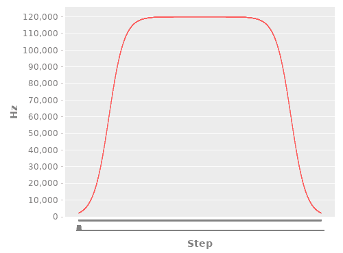
Because these functions take time to run and speed is critical to properly generating the waveform, I created a function to precompute the pulses.
It cuts the number of steps in two and flips it around so that there is an acceleration and deceleration.
This is a good example of some of the strengths of Clojure: in only 18 lines of code I can use first-class functions to easily pre-cache values and use the inline unit tests to document a potentially tricky corner case.
(with-test
  (defn precompute-pulse
    "Takes a pulse-generation function and turns it into a vector with the given number of steps"
    [pulse-fn steps]
    (let [halfway (vec (map pulse-fn (range 1 (inc (/ steps 2))))) ; split up the steps in half so that we can have acceleration and then deceleration. The purpose of this is to provide smooth motion and avoid missed steps.
          second-half (-> (if (odd? steps)
                            (pop halfway) ; if it's an odd number drop off the first step (the one that will end up in the middle) before reversing. This is so that we end up with the correct number of steps.
                            halfway)
                          (reverse))
          ]
      (vec (concat halfway second-half))
      ))
  (let [testing-fn (fn [step] (- step)) ; simple testing function the negative is so that we can easily observer that the testing-fn actually got called.
        ]
    (is (= (precompute-pulse testing-fn 4) [-1 -2 -2 -1]))
    (is (= (precompute-pulse testing-fn 5) [-1 -2 -3 -2 -1]))))
Here’s what the charted paths look like:
(defn make-plot [hz-vals]
  (let [hzs-for-dataset (vec (map-indexed
                              (fn [idx itm] [idx itm])
                              hz-vals))]
    (with-data
      (dataset ["Step" "Hz"] hzs-for-dataset)
      (line-chart "Step" "Hz")
      )))


(def four-turn-linear-plot (make-plot (precompute-pulse pulse-linear-fn 3200)))
;;(view four-turn-linear-plot)
(def four-turn-logistic-plot (make-plot (precompute-pulse pulse-logistic-fn 3200)))
;;(view four-turn-logistic-plot)
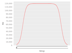
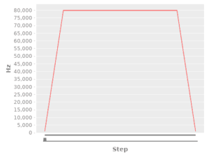
Results
Both the linear and logistic acceleration paths prevented lost steps from occurring.
Interestingly, I found the linear one to have a smoother observed acceleration, likely due to the increased ease of tuning.
Hopefully you’ve found this research to be useful for your own needs.
Feel free to re-use the code in this article under the terms of GPL v3.
For your convenience, I’ve put the ramp-up and ramp-down code into a GitHub repo.
Encountering challenges with motor control or IOT devices for your business’ needs?
Let us help: contact me at aaron AT stronganchortech.com